Issue
Article
Vol.28 No.3, July 1996
Article
Issue
Issue |
Article |
Vol.28 No.3, July 1996 |
Article |
Issue |
Object-Oriented Analysis and Design (OOAD) methods are rapidly getting a wide consensus. They are mainly based on a diagrammatic approach. Diagrams are intuitive, fast to learn and easy to use. However, they lack of a formal basis and their semantics is mainly descriptive. Furthermore, validation and verification of analysis specifications are, to a large extent, performed manually. Conversely, formal specification methods, such as Z or Larch, do not guarantee the same level of intuitiveness and have not been conceived for a diagrammatic representation.
In this paper we present a visual, diagrammatic OOAD method conceived to joining formality and intuitive user interaction. The method is organised in three layers. The external layer allows the user directly manipulate diagrams representing analysis specifications. The internal layer represents the formal model of the application being analysed. Then we have an intermediate layer that decouples the two, so that the external (presentation) layer has the independence from the formal layer that allows the flexibility to meet at the best the interaction needs of the user. The proposed method has been embodied in Mosaico, an O-O conceptual modeling tool developed at IASI-CNR.
Introduction
In the early stage of the development of an Information System, the analysis phase aims at specifying a conceptual model (or analysis model) of the application domain and the problem to be solved. A conceptual model is an application and domain model where all the details required by the implementation and programming activities are omitted. The analysis model [RBP*91] defines the objectives of the software development effort, clarifying the requirements, and guides the system design. Recent studies have shown that a significant part of errors are introduced in the analysis and design phases. Furthermore, specification errors are between 10 and 100 times more costly to fix during later phases of the software lifecycle than during the analysis and design phases [KSH92] [BP84]. This is one of the key reasons for concentrating on the improvement of the analysis process.
The analysis process is a highly interactive, iterative process in which tentative specifications are initially drawn, then revised, corrected, extended. This interaction intensive process requires a graphical user interface able to merge intuitiveness and ease of use with formality and semantic precision.
In recent years the Object-Oriented (O-O) approach has emerged as particularly suited for system analysis. This is true also for the database field, where application domains with complex entities are not easily modeled by relational systems. Furthermore, the O-O approach, based on the notions of object, relationship, and message passing, naturally leads to the use of graphs and diagrams for visualizing conceptual models.
Diagrams and graphs have been widely used in many field of the Computer Science, for modeling systems and, in particular, for analysis and design. Among the most popular modeling techniques, based on diagrams, we have: DFD (Data Flow Diagrams) [DeMa78] [WM85], SADT (Software Analysis and Design Techniques) [RS77], and for database modeling, Semantic Networks (such as NIAM [Rish92], ConceptBase [JMSV92]) and E-R (Entity Relationship) diagrams[Chen76].
In particular, in the area of Object-Oriented Analysis and Design (OOAD), all the leading methods use some kind of graphical notations. Among them we have: OMT (Rumbaugh et al.) [RBP*91], OOSE (Jacobson et al.) [JCJO92], OOA/OOD (Coad & Yourdon) [CY91], OOSA (Shlaer & Mellon) [SM88], DOOS (Wirfs-Brock et al.) [WWW90], OOAD (Martin & Odell) [MO92], OOD (Booch) [Booc94].
These methods have reached a great popularity also due to the availability of intuitive graphical notations, associated to analysis and design tools, supporting visual interaction with the systems.
The fundamental drawback of these methods is the lack of formal semantics: key concepts and the related notations are given on an intuitive basis. This leads to graphical specifications of the conceptual (analysis) object model that are sometimes imprecise and ambiguous. The ambiguities are often resolved during the design phase or, worse, during implementation.
Although the need for analysis methods based on a sound mathematical theory is widely recognised, the use of formal specification in the analysis process is controversial. In particular practitioners believe that formal approaches waive the advantage of the intuitiveness offered by diagrammatic and visual approaches [CEW92].
The work presented in this paper has been developed aiming at merging the advantages of both, the formal notations and graphical representations. To this end we propose a three layer architecture. The internal layer is represented by the formal analysis model, constructed by means of TQL++ [FM93], the conceptual language described in the next section. The external (presentation) layer is represented by the actual diagrams presented to the user (i. e., the application analyst). This is the level at which the interaction physically take place. Then, we have an intermediate level, the abstract diagrams level. This level captures the semantics of the diagrammatic model and the interaction with the user, independently of the physical details. It is based on an abstract diagramming language, TQD++ (Types and Queries Diagrams), which formally represent the gist of the diagrams presented (output) and the reactions to the actions of the user (input).
As anticipated, the majority of OOAD methods are based on a graphical notation lacking of formal semantics. This limitation starts to be recognised and there are proposal of methods which include both intuitive (diagrammatic) and formal (mathematical) notations, such as the tunable formalism, proposed in [CEW92]. Another approach is that of taking a well known diagrammatic approach and add formal semantics to it, as proposed in [BC95] for OMT.
Both the above approaches are based on a two layers architecture, that results inadequate to support a full interaction with the user. We follow a three layer architecture, similarly to what has been proposed in [BL89] with G-LOTOS, conceived for real time, parallel systems. In this paper we have a similar approach, conceived for the analysis and design of data intensive, Object-Oriented Information Systems.
Our work is based on the formal modeling language for O-O Database Applications, TQL++, which allows for the construction of the formal model of the application. Then we have an abstract diagrammatic notation, TQD++, to construct the abstract diagrams which captures the essence of the diagram model of the application leaving lout all the graphical details required to actually trace the diagram (referred to as concrete diagram).
Finally, we have the external layer, where the actual interaction with the user take place, implemented by an Automatic Layout Facility (ALF) tool [BDL95]. An ALF has the task to draw an instance of abstract diagram (i.e., concrete diagram), with all the visual details and beautification aimed at achieving an effective user interaction.
The work presented in this paper has been implemented and is currently under integration with Mosaico [LM93], a conceptual modeling environment for the analysis of OODB applications.
The remainder of this paper is organized as follows. First we give a brief summary of TQL++ and its formal basis. Then we illustrate the proposal for a graphical notation, TQD++, and its correspondence with TQL++ grammar. Finally, we conclude the paper summarizing a few implementation issues, followed by an overview of future research.
In this section the conceptual language TQL++ is briefly illustrated. For a more complete description of the language, please refer to [MP95], [FM94]. The language is characterized by all the main features of Object-Oriented (O-O) paradigm (such as typing, inheritance, object identity, message passing), but avoids all the technical details found in existing development and programming languages. TQL++ is the language on which Mosaico [LM93], an environment for conceptual modeling of O-O database applications, is based. In a database application model, constructed by using TQL++, there is a clear separation between the intensional and extensional components. The intension of a database application, i.e., a TQL++ schema, is represented by a collection of types. The type is the fundamental element of the specification of a database application in TQL++. Types contain the description of the structure of the objects that will populate the database, the specification of integrity constraints and, finally, the actions, i.e. the definition of the behaviour of the objects.
We start introducing a few examples of the structural component of TQL++ types.
A user defined type has a name (type label) and is defined by means of a tuple of typed properties. The ISA construct allows one or more supertypes to be specified. A property can be typed in different ways, by using: (i) a basic type name, such as integer (int) or string (str); (ii) an explicit set of values, given either by enumeration, as in car.maker, or by specifying the extremes of an interval, as in student.age; (iii) a tuple of typed properties, as in person.address; (iv) finally, a type label, as in car.owner and student.vehicle, establishing an explicit link between two types (an association or relationship). Associations forming a cycle allow the definition of recursive types. Please note that a property can be single- or multi-valued. In the first case only one value is allowed for the instances, in the second case instances can take any number of values, like for person.tel.
In the Figure 1, the formal syntax of the TQL++ structural component is presented.
Figure 1 -- TQL++ structural component: formal definition
In defining the structural part of a type it is possible to introduce, cardinality constraints on multi-valued properties. The following figure reports the corresponding syntax of TQL++.
Figure 2 -- Cardinality Constraints
In addition to the structural specification, the static component of a type requires the specification of explicit integrity constraints. They are boolean expressions of elementary (binary) conditions. An elementary condition has two comparands, essentially two properties, and a binary operator q ("q" represents a comparison operator such as: "=", "<", ">", ...).
Each argument of the binary condition is represented by a path, i.e. a sequence of properties constructed by using the dot-notation. A "theta-constraint" is assumed to be universally quantified over the extension of the compared terms (two set of values or, more generally, two sets of objects). In the syntax, the key-word "this" refers to a single object, for which the constraint must hold. Since each constraint is applied to every object in the class, "this" can be seen as a pseudo-variable ranging over the entire class. A type label denotes an entire class. When the right hand term of the comparison starts with the type label of the type being defined (see ic2 in example 3), the type label indicates the corresponding class less the object denoted by "this" (referred to as current object).
In example 3, six explicit constraints are reported. An object that belongs to a given class, say person, must satisfy all the constraints expressed in the corresponding type. In particular, in the example, ic1 is a constraint that refers to the values of the current object in the class person (intra-object constraint), while ic2 compares the social security number of the current object with the same property of all the other objects in the class person (intra-class constraint). The integrity constraint ic3 makes use of the dot-notation to navigate across objects. In particular, it imposes that the age of all the children of any person object is less than a given constant (intra-class constraint).
Dot-notation also allows one to refer to other classes, and ic4 is an example of this possibility (inter-class constraint). In particular, it compares properties of car objects referred by objects of the person class. The constraint ic5 expresses that, for a teacher, the sets of his/her students and children must be disjoint. This constraint requires a comparison between subsets of the class person.
Conditional constraints represent a key feature of TQL++. In the example below, ic6 describes a constraint that must be verified only for a subset of the employee objects, namely the ones having no children. This sort of constraints plays a primary role since it is a sort of exception handler that allows the Schema to reduce the necessity of subtyping.
In specifying the constraints, it is possible to introduce user-defined predicates (usdef_pred). In the example, empty is used to test if a set-valued attribute contains any element. Furthermore, we have a set of system functions, such as count, which returns the cardinality of a set-valued attribute.
In the following figure, the syntax of explicit integrity constraints is formally presented. The semantics of TQL++ allows the application of the comparison operators to both, single- and multi-valued operands. In general, the first six q-operators are applied to single-valued and the last six to multi-valued operands (note that equality and inequality are valid for both sorts of operands). The symbols "in", "^" and "#" stand for the set-theoretic operators of inclusion, not-empty intersection, and disjunction, respectively. The g-operators represent elementary algebraic operations on numeric values (the first four) and on sets (the last three, which compute intersection, union and set difference, respectively). The g-operators can be used within a comparison expression.
Figure 3 -- TQL++ explicit integrity constraints: formal definition
Behaviour Specification
In TQL++, the behavioural part of the application is specified by defining the actions associated to each type in the schema. In the target system, the actions will be implemented as methods.
An action has an header (name and signature) and a body. The latter is defined, essentially, supplying two sets of integrity constraints and commands, named pre- and post-conditions. They, respectively, define the range and the domain of the action, seen as a function over database states. Both, range and domain, are subsets of the database state space, in which legal states are defined by the invariants represented as implicit and explicit constraints. The set of action headers are gathered in the protocol of the type, which reports the interface with typed arguments.
Here the definition of the TQL++ actions follows.
Figure 4 -- TQL++ Behavioural Component: Formal Definition
The following example shows a portion of the action specification for the type library. In particular, the example reports the action loan which requires, as precondition, the presence of the book on the shelf and, as postcondition, the fact that the book is no more on the shelf.
Please, note the use of the user-predicate give_to, that modifies the state of the database.
In this section the main issues concerning TQD++ (Types and Queries Diagrams), a diagrammatic notation for TQL++, are presented.
TQD++ has been conceived with the intent of unifying the advantages deriving from the joint use of formal and graphical notations, in the construction of an analysis model of an application system.
The work is based on an abstract syntax [Moss90] for the definition of visual elements and diagrams. According to this approach, a diagrammatic specification is constructed in term of abstract figures that are assembled to compose an abstract diagram. An abstract figure is a formal (textual) definition of a visual symbols, without any reference to the visualization details. As already mentioned, the task of visualizing an instance of abstract diagram (a concrete diagram) is performed by an ALF (Algorithm Layout Facility) tool, capable of interpreting abstract figure definitions and render them on the screen (or trace them on paper). This solution yields the mentioned three layer architecture, with a clear separation between the semantic content of a diagram and its actual representation, with all the aesthetic issues.
Abstract diagramming is based on a constructive method. It starts with the definition of the basic figures, corresponding to the basic constructs of the underlying object model (the object model of TQL++). Then, a set of composition rules is defined, aimed at the construction of complex, higher level figures.
The use of this method has been guided by two fundamental criteria. One concerns the transparency and ease in understanding the TQD++ symbols: in principle it should be possible to interpret and draw manually TQD++ diagrams. The second concerns the possibility of improving the human-computer interaction by avoiding complex, overloaded diagram models. Then the information that cannot be modeled diagrammatically is represented by associated textual annotations (in TQL++). The latter are not part of the diagram and are presented in separate windows.
In summary, we propose to the designer an hybrid formalism, for the specification of an analysis model, obtained by a careful integration of TQL++ and TQD++ notations.
In the next subsections the details of the TQD++ notation are illustrated starting with the description of the basic figures. The rules of the abstract syntax (concerning essentially the composite figures) are represented by Prolog-like clauses, in which the semantics of the corresponding symbols is denoted by the functors (i.e., predicate names).
The set of the basic figures of TQD++ is presented starting from the elementary symbols and relating them to the TQL++ basic constructs (such as: type, association, ISA hierarchy).
In TQD++ there are two fundamental classes of symbols: Containers and Links. The containers are represented by unary predicates, while links are represented by binary predicates. The following table relates the basic abstract symbols (TQD++ predicates) to the concrete (graphical) symbol. The third column (Description) is an informal mapping to the semantics, supplied by TQL++.
Table 1 -- The Basic Symbols of TQD++
TQD++ Predicate Symbol Description
rounded_box(A)Type oval(action)
Action skew_box(A)
Constraint straight_box(A)
Property circle(K)
Constant thick_arc(A,_)
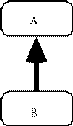
ISA Association source_head_arc(A,_)
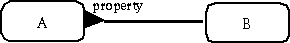
Association by property hollowCircle_arrow(A,_)
Info accessed by simple path solidCircle_arrow(A,_)
Info accessed by complex path plain_arrow(A,_)
Element of complex path plain_arc(A,_)
Association by message passing plain_edge(A,_)
Association by constraint
Starting from the basic, elementary figures presented in the previous subsection, it is possible to construct composite figures and diagrams. To this end we need to add a few basic elements: graphical relationships and adornments.
Two relations have been defined to compose basic figures into aggregates. They correspond to two graphical composition mechanisms: the first is embedding, which allows figures to be nested; the second is aggregation, which is based on the adjacent placing of graphical elements. The corresponding TQD++ predicates are: in(a,b) and composed_by(a,[list]), respectively.
The first indicates that the figure identified by a is contained in the figure identified by b. The second indicates that the figure identified by a is composed by the figures whose identifiers are contained in the list.
The adornments are not basic figures but are presentation features introduced to add visual characterization to the figures. In particular, unary and binary adornments have been defined.
Unary adornments give information on the status of the figure identified by id. For example, source_selected(id) asserts that the figure identified by id has been selected as a source of a message passing association by the user who, for instance, is exploring a message passing diagram. The effect of this interaction will be a colour change of the selected figure. In this type of interaction, also the corresponding action and type (targets of the message) get automatically selected, in response to the user selection of the message source.
The binary adornment text(id,string) asserts that the string is added as textual information to the figure identified by id.
Composite figures in a TQD++ diagram are constructed by using lower level figures and composition rules. In the composition rules there are necessary and optional components. The latter are enclosed in square brackets. Each composite figure has an identifier that is contained in the head of the corresponding rule as argument.
In the rest of this subsection we give four examples of composite figures that correspond to key constructs in the TQL++ object model.
Each composite figure is presented by showing the TQL++ code, the TQD++ sentence (the abstract figure) and a drawing that shows the concrete figure i.e., the instance of the abstract figure.
action_box(A) is a composite figures constructed as in figure 5. It allows the explicit representation of actions defined within a type.
Figure 5 -- The action_box Predicate
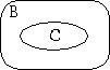
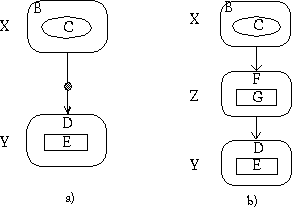
The property_type_box(X) is a second composite figure, constructed as in figure 6.
Figure 6 -- The property_type_box Predicate
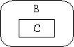
In Figure 7, we see that the TQD++ predicate simple_ISA_hierarchy is constructed in terms of basic symbols (see Table 1) and the relation composed_by. The predicate rounded_box(B) could be absent. This situation reflects the case of an incomplete schema, where there is the construct typeA := ISA typeB, but typeB has not yet been defined. This allows the construction of diagrams in which a certain variety of schema incompleteness is visualized.
Figure 7 -- The ISA Hierarchy
This composite figure is constructed by using basic symbols, the relation composed_by, and the adornment text. Also in this case there are optional predicates. In particular the predicate text(C,<card>) allows the specification of a cardinality constraint for multivalued properties. It is expressed as a pair of integer, according to the TQL++ syntax.
Figure 8 -- The Association by Property
At the level of message_association composite, action_box can be treated as a basic figures (as shown in Figure 9-a). This is one of the key issues of the compositional approach of the abstract diagramming proposed in this work. If needed, the diagram can be enriched by exploiting the information carried by the action_box clause (see Figure 9-b and Figure 9-c). We see, in particular, that the OR construct, at the end of the action_box clause (constructed by using semicolon ";"), allows for the definition of the visual status of the oval(C): (i) unselected, (ii) selected as source of message_association, (iii) selected as target of message_association.
Figure 9 -- The Association by Message Passing
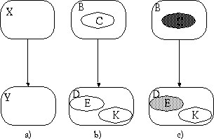
a) b) c)
This composite figure concerns those situations in which an object, during the execution of an action, performs an access to external information. This figure does not map to one specific TQL++ construct. In fact, by information access we mean a variety of command patterns, specified within a TQL++ action body, whose semantics is the access to one or more object data. One of such patterns is an access path constructed with the dot notation. Another is the scanning of a set (such as a class or a multivalued property) with the FIND command to perform, for example, an object selection.
An access path can be simple, when a class or a property is reached via a path of length one, otherwise it is complex. The latter situation is presented in Figure 9. Looking at the TQL++ code, we see that the path is composed because propG is typed with a user-defined type (in Figure 10 it is typeD).
To represent a complex path, two visual alternatives are allowed. The first represents the path only indicating the source and the destination (this is the contracted option -- Figure 10-a). Alternatively, it is possible to represent the intermediate nodes of the path (this is the expanded option -- Figure 10-b). Obviously the underlying TQL++ code is the same, while the TQD++ predicates represent the two alternatives.
Figure 10 -- The Information Access
The implementation of a diagramming service for the visual modeling of an analysis specification is one of the current activities within the Mosaico project at IASI-CNR. The Mosaico project concerns the development of an environment for the analysis and conceptual modeling of Object-Oriented Database Applications.
As already mentioned, visual formalisms have been conceived to improve user interaction and enhance the usability and intuitiveness of the modeling environment for complex applications analysis.
The implementation of the diagramming facility presented in this paper has been divided into two phases. The first phase concerns the visualization of an analysis model defined by means of the TQL++ formalism. The second phase consists of the opposite operation: the definition of a TQL++ conceptual model starting from a diagrammatic input. Figure 11 presents an overview of the part of Mosaico concerned with diagramming. The architecture appears as a sort of loop, which starts and ends at the GUI. In the phase being currently implemented (visualization) the loop is traversed counter-clockwise.
Figure 11
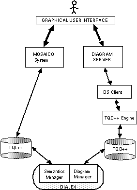
The designer specifies the analysis model with TQL++ and the system, through the DIALEX module, translates the key structures to an abstract diagram. The latter is then delivered to the Diagram Server, which is responsible for the actual drawing of the concrete diagram.
DIALEX (DIAgram -- LEXical Converter), which is the central element of the architecture, maps TQL++ constructs into TQD++ abstract diagrams. As the figure shows, it is composed by two modules. The first (Semantics Manager) analyzes the TQL++ schema and recognises the relevant construct to be drawn. The second (Diagram Manager) builds the base abstract diagram in which all the basic TQD++ figures (containers and links), relationships, and adornments are included (but not the composite figures). The base abstract diagram is then used by the TQD++ engine which, by means of the composition rules of the abstract syntax, reconstructs the full abstract diagrams and gives the drawing commands to the specific ALF tool (this part is modularized, to allow the system to interface different ALF tools).
The ALF tool selected in our implementation is Diagram Server. It is a network server offering to its clients a rich set of options in diagram drawing. In our implementation we developed a specific DS client, which is driven by the TQD++ engine.
This architecture shows an implementation of the three layers approach. Preliminary experiments have shown that the flexibility of this approach leads to effective user interactions in the difficult task of Object-Oriented analysis and design.
DIALEX and TQD++ engine, as well as the rest of Mosaico, have been implemented on a Sun workstation (SparcStation 20) running Solaris 2.4, using SWI Prolog and XPCE development system, developed by the University of Amsterdam.
The future research activities will be addressed, mainly, towards two directions. The first direction concerns the completion of the visual environment for Object-Oriented analysis and design. It concerns the implementation of a graphical, direct-manipulation environment that allows the construction of the diagrammatic model of the application. This graphical model will be automatically checked and translated into the appropriate TQL++ code. This is represented by the clockwise traversal of the architecture in Figure 12. It must be noted that the choice of implementing first the counter-clockwise traversal is motivated. The characterization of the abstract figures starting from the TQL++ constructs ensures a clear understanding of their semantics giving, therefore, the required isomorphism between abstract diagrams and TQL++ conceptual models.
The second direction concerns the characterization of higher level conceptual constructs, in terms of abstract diagrams. We are currently studying a number of higher level construct, besides the ones already defined, such as: transaction, data-flow structure, and use-cases, that have a relevant role in modeling complex application and are provided by major OOAD methods.
IASI-CNR, Viale Manzoni 30, 00185 -- Roma, Italy
missikoff@iasi.rm.cnr.it
pizzican@iasi.rm.cnr.it
Issue |
Article |
Vol.28 No.3, July 1996 |
Article |
Issue |